If you've gotten here, then you're interested in how this thing works. Hang on to your EE degree and sit back.
First, I'll start with the disclamer that this device produces high voltages that can shock you. Also, this device can't be legally hooked up to the PSTN as there is all sorts of red tape you need to go through to get the device registered for that.
A handy thing to have is a printed copy of the schematic ( here in PDF format )
The basic functional blocks of the English ringing converter are pretty simple. It has a ringing detector, a loop detector, a ringing generator, a power supply, and a microprocessor for control.
Theory of operation:
American ringing is a 2 second on, 4 second off ringing voltage at 20Hz. English ringing is 400ms on, 200ms off, 400ms on, and 2 seconds off ( a double ring ). It is also at 25Hz and and a slightly lower voltage ( 80VAC vs 108VAC ).
When the converter detects ringing on the line, it disconnects Rosemary's phone from the line and switches the telephone over to the internal ringing supply. It then generates 25Hz ringing voltage by driving 24 volts into a split bobbin transformer backwards to generate the high voltage ringing. When Rosemary answers her phone, the converter detects the loop current and disconnects the phone from the ringing supply and connects it back up to the network. In the case of Rosemary initiating a call, no action is required on the part of the converter, as the phone is normally connected up to the network by default.
The first thing you need to do is detect inbound ringing from the network. In the US, this is 108VAC at 20Hz with a cadence of 2 seconds on and 4 seconds off. This is done with a .47uF 250V capacitor, a 2200 ohm resistor, and an optocoupler. The extra zener diodes prevent false tripping of the ringing detector for anything less than about 35VAC. This circuit also provides a REN of 1.0.
The next thing you need to detect is an off-hook condition on the phone. This is done with a loop current detector that consists of an 82 ohm resistor and optocoupler. The resistor and optocoupler have about a 1.5V forward drop when loop current is flowing, but have no AC impedance. This is important because telephone lines have lots of common mode noise on them ( mostly 60Hz and AM radio components ). Since it presents almost no AC load, the detector doesn't unbalance the line and cause hum in the phone.
The biggest problem I had was how to control the whole thing. The control block sat for a year or so as an empty block on the schematic. The two choices were to either do a small FPGA or use a programmable microcontroller. The logic was very simple, but in the end I decided to go with an Atmel 89C2051 microcontroller. I've done a lot of work with the 8051 architecture in the past, and it was fairly simple to write the code for this. I was quite surprised that the code turned out to be almost 1K in size for such a simple function.
The two input signals are fed into the microprocessor. The microprocessor controls both a ringing relay and the drivers for driving the ringing generator. I picked an Atmel 89C2051 for the job because I'm comfortable with the 8031 architecture, and the 24-pin device was perfect for what I needed. Using the power down mode when not busy, the processor typically draws less than 1mA during operation. I also run the processor at a slightly slower 6.144 MHz speed that gives 2.048uS per processor cycle. I included a LED wired to one of the processor I/O ports for debugging purposes. It turned out to be real useful. I wrote the code to pulse out what state it was in in the finite state machine. I then hooked up a scope to the LED and could monitor what states the code went to for different inputs. It only took three revisions of the code to get the bugs out.
When we want to ring Rosemary's phone in the English way, we disconnect the phone from the network with the relay and connect it to our ringing supply. The relay is wired so that in the default unpowered state, the phone is connected to the network. Our ringing supply is just a split bobbin transformer wired backward and fed from the middle on the primary side with 24 volt battery. This allows us to use the loop detector to detect when the phone has been lifted, even when we are in the middle of a ringing cycle. On the primary side of the transformer, we drive the primary coils in opposite phases with the 24 volt battery through either strong or light drivers. This allows us to generate a "stepped" sine wave that approximates the 25Hz 80VAC ringing of the English network. I also included a pair of TIP125 darlington drivers as I was planning to use an EWC transformer with a lower DC resistance, but unfortunately, they were acquired, and their excellent transformers are no longer availabe. I was also planning to do a software PWM driver output to the secondary side, but the software got a bit hairy.
The ULN2003 darlington drivers are handy devices. They will individually sink up to 500mA of current, can be driven by low voltage logic, have a built in flyback diode, and include 7 devices in a DIP package. In this case, we drive the devices through current limiting resistors ( 82 and 8.2 ohms ) to vary the amount of current in the secondary winding of the transformer. The 8.2 ohm resistors act mostly as current balancing devices so that the one ULN2003 driver will not hog the current from the other one.
Here is a scope trace of what the output of the ringing generator looks like. Note that at the trigger point ( one division over from the left of the screen ), the relay cuts in and 24 volts is present on the line. About 22mS later we start the ringing cycle. The odd shape of the stair-step waveform is due to the inductive nature of the transformer. The good news is that most of these frequency components are way above the 25Hz fundamental that the telephone ringer is tuned for, so are of no consequence. The ringing voltage is 88VAC imposed on top of 24VDC which is pretty close to the 80VAC that I was designing for.
As soon as we detect loop current, we disconnect the phone from the ringing supply and connect it back up to the phone network. The off-hook condition is then presented to the network, and the call is cut through.
When Rosemary initiates a call with the English telephone, no action is required on the part of the converter, it just sits passively by while is sees loop current. When loop current goes away, it gives the line two seconds to clear down and then goes back to looking for inbound ringing.
Software Design:
The software was desgined as a finite state machine that is called every 5mS. The states that the software goes through are shown below:
When the microprocessor powers up, it places the state machine in the reset state. This resets the variables, disables the ring relay and the ringing drivers, and goes to the idle state.
In the idle state, we look for either loop current or inbound ringing. If loop current is detected, it means that Rosemary has picked up the phone and is placing a call. We go to the off-hook state. If we detect ringing from the network, then we pick ( seize, close ) the ringing relay to disconnect Rosemary's phone from the network and connect it to our own ringing generator. We then go to the pick ring relay state. We also set the ringing abandon timer to 4.5 seconds. If this timer every gets decremented to zero, we will know that the caller abandoned the call and we need to stop ringing the phone. The normal off cadence in the US is 4 seconds, so we give ourselves and extra 500mS just in case the timing is a little off at the exchange. This timer is reset to 4.5 seconds each time we detect ringing on the line.
In the pick ring relay state, we sit here for 30ms to give the relay time to switch and for the line voltage to settle down. The relay is a generic 2-form C dip relay with a 24V coil. It switches both sides of the line to insure complete isolation between the ringer circuit and the telephone network. After 30mS, we go to the 1st 400ms ring state.
In the 1st 400ms ring state, we drive the four darlington drivers ( ring_ph(1/2)(H/L) ) in a manner to generate a stair stepped psuedo sine wave at 25Hz. The drive pattern of the drivers is shown below:
The light drivers are pulling about 220mA ( 30V / 52+82 ohms ) through each secondary coil of the transformer and the heavy drivers are pulling about 460mA ( 26V / 52+4 ohms ). The reason I've used a lower supply voltage for the heavy driver is that the wall wart that supplies 24 volts ( nominally ) is very poorly regulated and droops quite a bit under load ( not really a problem ). The duty cycle for the light drivers is 220mA at 25% and the heavy drivers each sink 230mA at a 13% duty cycle. Both of these are well within specs for the ULN2003 thermal capabilities.
We cycle through the ringing states ( 1st ring, 200ms delay, 2nd ring, 2 second delay ) until either the call is answered ( loop current detected ) or the ringing abandon timer reaches zero ( the caller hung up ).
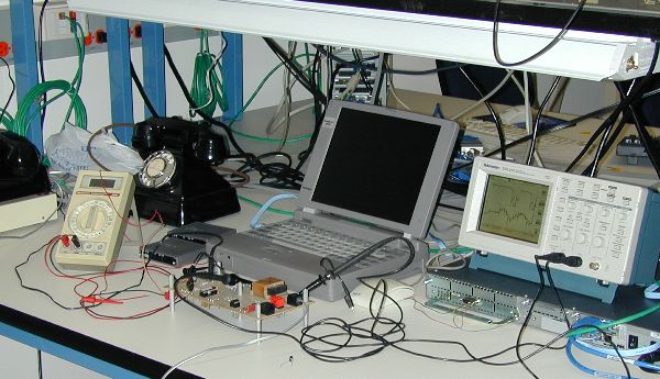
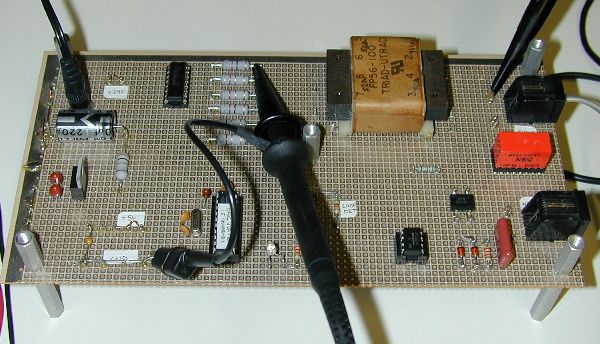
Here are some photos of the breadboard and the phone schematics:
The phone schematic:
and the bellset 31 schematic:
My current wiring for the phone and dial ( not sure if it's correct, it has a lot of sidetone ):
Back to the English Ringing Converter Project Homepage
Back Home to Strato Loft